How to Use a Bearing Splitter: 5 Easy Steps
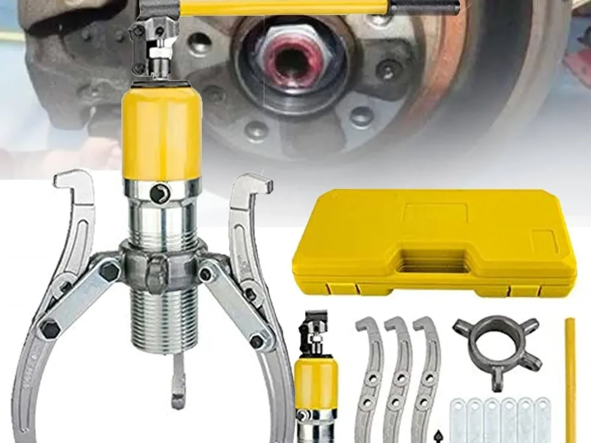
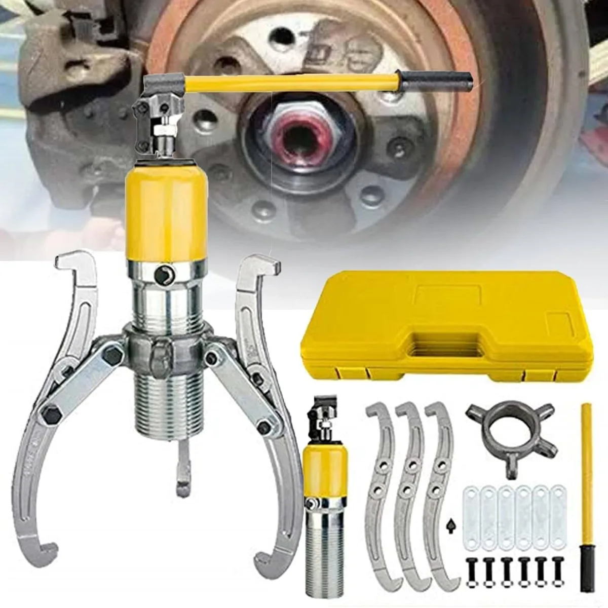
Image source: Bing (Web (fair-use with source credit))
Why Visual Alignment Is the Make-or-Break Step
You cannot rely on feeling the tool into place. A millimeter off-center causes the arm to bind on the raceway. This binds the mechanism and twists the shaft.
Visual confirmation means the yoke gap is parallel to the shaft plane. You need a straight edge or a laser level for large spindles.
If the arms look level to the eye, they might still be tilted. Tilted arms create a momentary torque that damages the seal groove. This is why we recommend checking the profile from two angles.
You look down the shaft length. You then look from the side. Both views must show equal clearance.
The visual cue is simple. The arm tips should hover 2 to 5mm above the shaft surface. This gap prevents contact during the initial seating phase.
You want the pins to contact the inner ring, not the outer housing. Skipping this visual check is the most common error. It leads to deformed housings and wasted labor.
Identifying the Right Splitter for Your Shaft
Size matters more than brand. Your tool must exceed the shaft diameter by at least 2mm. This clearance lets the arms rest on the bearing face.
A splitter that is too small will not clamp correctly. A splitter that is too large offers poor leverage.
You also need to match the force rating. Light automotive bearings need manual splitters. Heavy industrial spindles require hydraulic units.
Manufacturer specifications list the maximum working load. Never exceed this limit. Overloading bends the yoke arms permanently.
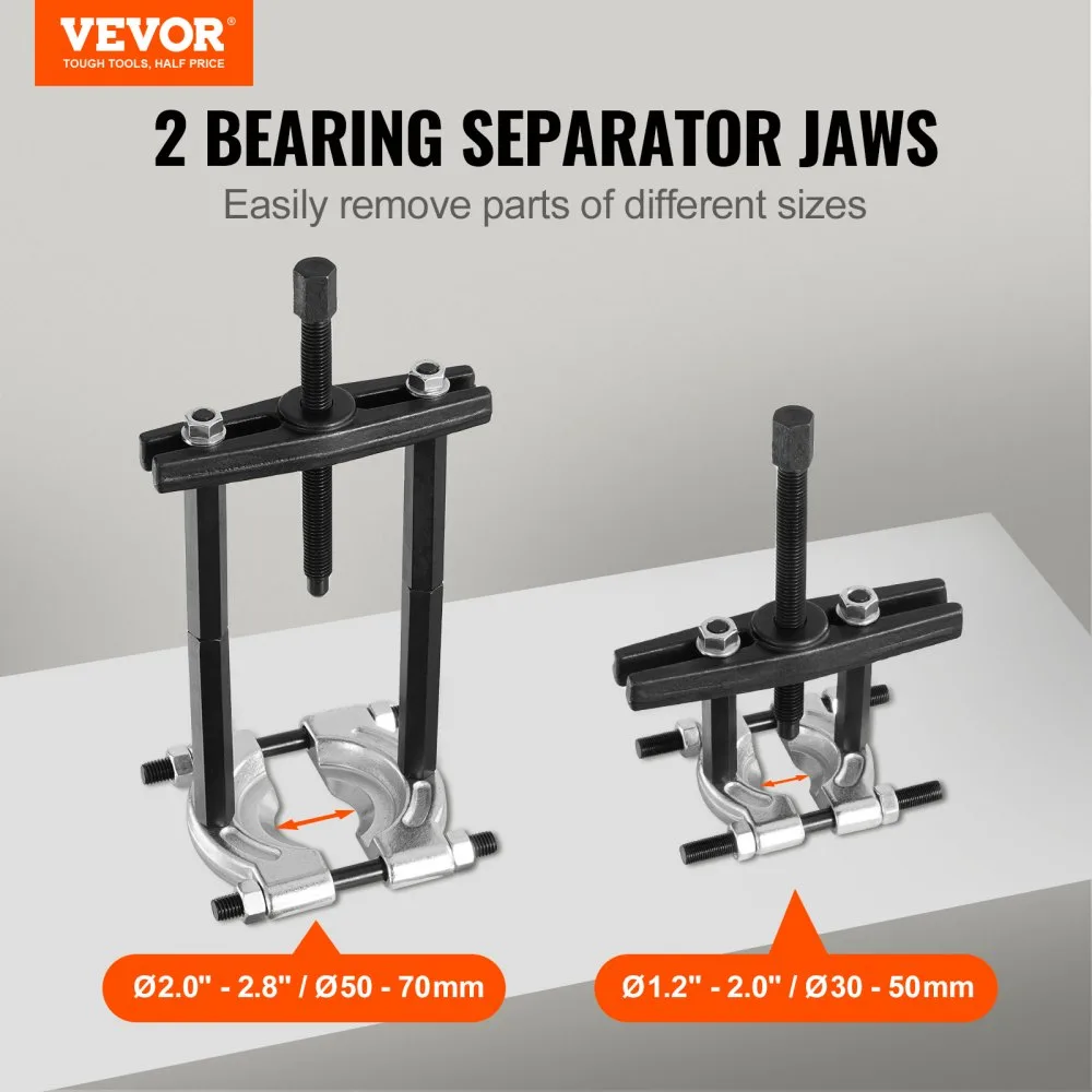
Consider the threading standard. Most tools use metric or imperial threads. You must match the drive nut to the pin threads.
Mismatched threads strip quickly under load. Check your tool inventory before starting the job. We recommend keeping a mix of M16 and M20 pins.
These cover most common spindle sizes. If you are unsure of the fit, refer to a puller selection chart to verify dimensions quickly.
The Setup: How to Position the Yoke and Arms
Start by securing the machine frame. The splitter needs a solid anchor point. The reaction force is equal and opposite to the pull.
If the frame moves, the tool slips. This creates a dangerous kickback. Lock out the power supply first.
Then clamp the yoke to a stable surface.
Next, slide the arms onto the yoke. The pins must thread into the central hub. Use a hex key to tighten the hub lock.
This holds the pin tension during removal. You want the arms to swing freely. But you do not want them to fall out.
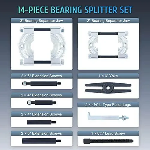
Position the arms around the bearing. They must contact the inner ring face only. If the arm hits the outer race, stop.
Redo the alignment. This is critical. Forcing it on the outer ring damages the housing bore.
Once aligned, tighten the arm clamps. You want rigid support. The pins do the work.
The arms just guide the force. If you are using a smaller tool, check our guide on external vs internal pullers to understand the difference in application.
Executing the Removal: Jacking Sequence and Force Control
You will turn the drive nut clockwise. This pushes the pins out radially. The pins contact the inner ring.
They apply axial force to the shaft. You should move in small increments. Do not blast through the whole rotation.
Listen to the tool. A smooth rotation means good contact. A grinding sound means misalignment.
Stop and re-center. You want the bearing to slide off slowly. Sudden release creates a shock load.
This can snap the shaft or the tool.
Maintain steady pressure. If the bearing is tight, add a few turns. Then pause.
Let the friction heat dissipate. This prevents annealing the shaft steel. If the bearing is galled, do not force it.
See the next section for that specific scenario. You want a clean slide-out. If it fights you, check your puller tool guide for alternative methods.
Handling Galled Bearings and Corroded Housings
Sometimes the bearing will not move. Corrosion welds the inner ring to the shaft. This is called galling.
You cannot pull it with standard force. You need a different approach. Do not increase the jacking force beyond the tool rating.
You will bend the arms. Instead, apply penetrating oil to the interface. Let it soak for an hour.
Then use gentle thermal expansion. Heat the bearing outer ring slightly. This expands the ring and loosens the seal.
It does not heat the shaft. The gap allows the bearing to slide off. If you must use more force, ensure you have a complete guide to types and sizes to select the right heavy-duty option.
Never exceed the rated tonnage.
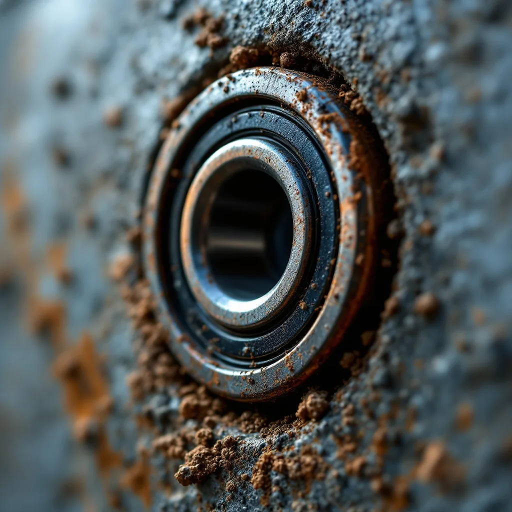
If the housing is corroded, inspect it before removal. Rust weakens the metal. The bearing removal might strip the thread.
Mark the orientation of the housing. You may need to replace it. If you are struggling with a stubborn seal, check our tips on essential automotive specialty tools for alternative extraction methods.
Safety Checkpoints and Common Pitfalls
Always wear eye protection. Grease mist and metal shreds fly. A single chip can damage your vision.
Wear gloves to prevent pinch points. Your hands are near the moving arms. Keep them clear of the shaft path.
Lock out the power before starting. A spinning shaft kills or mangles. Follow OSHA guidelines for machine isolation.
Post a warning sign. Tell nearby staff not to restart the system.
Avoid these common errors.
- Forcing the tool: Never exceed the rated tonnage.
- Uneven loading: One arm taking all the force bends it.
- Ignoring clearance: The yoke must not touch other parts.
If the tool feels loose, stop. Tighten the clamps. A loose setup creates dangerous kickback.
Keep your footing stable. A slipped tool can twist the shaft violently. Always check the automotive pullers specs if you are working on vehicle components.
Troubleshooting Tool Limitations
Sometimes the tool simply cannot reach. Check the space behind the bearing. You need room for the yoke depth.
If it is tight, switch to a lower profile design. Or use a smaller jaw size. This reduces the overall height of the tool.
What if the threads strip? Do not use a damaged pin. Replace it immediately.
Stripped threads fail under load. This snaps the pin. You can buy replacement pins from most manufacturers.
Match the thread pitch exactly.
What if the bearing is too large? The tool will not generate enough force. You need a higher tonnage unit.
Or a hydraulic press. Do not modify the tool. Modifications weaken the yoke.
Check our guide on how to choose a puller for the right capacity.
If the bearing slides off but stays stuck, the issue is corrosion. Use the thermal method described earlier. Do not hammer it.
Hammers damage the shaft surface. You want a smooth finish for the new bearing.
FAQs
How much force does a bearing splitter need?
Most manual splitters handle up to 10 tons. Hydraulic units go up to 50 tons. You calculate the force based on shaft diameter.
Larger shafts need more axial force. Always stay within the tool rating.
Can I use a bearing splitter on plastic housings?
No. The hard steel arms will crack plastic. Use a specialized plastic safe puller instead.
Or build a custom wooden yoke. Protect the housing surface at all costs.
How do I prevent shaft damage during removal?
Keep the tool centered. Avoid twisting the shaft. Use penetrating oil for stuck bearings.
Check the shaft with a micrometer after. Any scoring requires machining or replacement.
What should I do if the arms bend?
Stop using the tool immediately. Bent arms create uneven force. They can snap under load.
Replace the yoke. Do not attempt to straighten it. The metal properties change when bent.
Is a splitter better than a hammer?
Yes. Hammers cause sudden impact damage. Splitters offer controlled, gradual force.
This protects the shaft and housing. Use hammers only for non-critical, loose bearings. For press fits, always use a splitter.